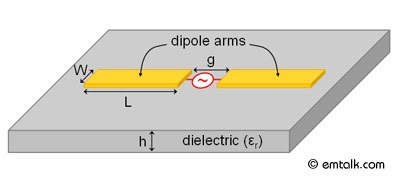
In this tutorial, a printed dipole antenna with a differential feed is modeled and simulated in Ansoft Designer. The printed dipole antenna is often used in planar microwave radiative applications that require an omni-directional pattern. The model of the printed dipole is shown in Fig. 1. The dipole arm's width (W) and length (L) will be optimized for 3.0 GHz operation, while the feed gap (g) and the substrate height (h) will be fixed. The model and simulation setup are outlined. The methods used to setup the simulation are outlined. In particular, the following topics are covered:
Layers Setup
Model Setup (Parameterization)
Excitation Setup
Analysis Setup
Plotting Results
Optimization
Layers Setup
Model Setup (Parameterization)
Excitation Setup
Analysis Setup
Plotting Results
Optimization
First load up Ansoft Designer, then go to Project > Insert Planar EM Design to launch the MOM simulator. A window will appear asking you to choose a layout technology (substrate) as shown in Fig. 2. Pick MS - RT_duroid 5880 with a height of 0.010 inch. Once, you have chosen the technology, a project window will appear. Before we can setup the model, we need to remove the ground plane. To do this, go to Layout > Layouts and the Edit Layers window will appear. Select the ground layer and then click on Remove Layer. The Edit Layer window should look like Fig. 3, when the ground later is removed
No comments:
Post a Comment