Sunday, November 22, 2009

S-Parameter Simulation: Schematic Simulator


Agilent Advanced Design System (ADS) is an industry standard microwave engineering computer-aided-design (CAD) program. Agilent ADS allows microwave engineers to analyze, design, and simulate active and passive microwave components and systems. In this tutorial, a microstrip transmission line will be designed and analyzed. It should be noted that there are two ways to design/simulate in Agilent ADS; schematic (equation-based) or full-wave (Method-of-Moments). The microstrip line will be designed and simulated using the schematic simulator in this tutorial, while in Tutorial 2 a full-wave simulation will be performed using Agilent ADS’s full-wave simulator, Momentum.
Microstrip Transmission Line Design Values
Operational Frequency: 1 GHz to 5 GHz
Substrate: 2.2 Permittivity and Height of 1.57 mm
Characteristic Impedance: 50 Ohm
Electrical length: 90 degrees at 2.4 GHz.
Simulation Setup
Open up Agilent ADS, the window shown in Fig. 1 will pop-up onto the main screen. Click on Create a new project and give it a name; make sure not to use any spaces and choose the units for the design

Printed Dipole Antenna (Differential Feed)


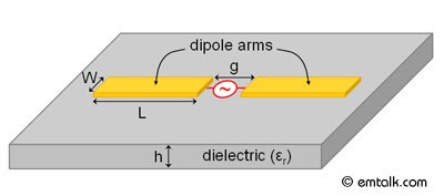
In this tutorial, a printed dipole antenna with a differential feed is modeled and simulated in Ansoft Designer. The printed dipole antenna is often used in planar microwave radiative applications that require an omni-directional pattern. The model of the printed dipole is shown in Fig. 1. The dipole arm's width (W) and length (L) will be optimized for 3.0 GHz operation, while the feed gap (g) and the substrate height (h) will be fixed. The model and simulation setup are outlined. The methods used to setup the simulation are outlined. In particular, the following topics are covered:
Layers Setup
Model Setup (Parameterization)
Excitation Setup
Analysis Setup
Plotting Results
Optimization

First load up Ansoft Designer, then go to Project > Insert Planar EM Design to launch the MOM simulator. A window will appear asking you to choose a layout technology (substrate) as shown in Fig. 2. Pick MS - RT_duroid 5880 with a height of 0.010 inch. Once, you have chosen the technology, a project window will appear. Before we can setup the model, we need to remove the ground plane. To do this, go to Layout > Layouts and the Edit Layers window will appear. Select the ground layer and then click on Remove Layer. The Edit Layer window should look like Fig. 3, when the ground later is removed

Dispersion Diagram I: Parallel Plate


The parallel plate waveguide is one of the most common waveguides studied in electromagnetics textbooks. A parallel plate waveguide consists of two metallic plates separated by air or a dielectric substrate. The plates are considered to be infinite in extent, but in reality this is not possible and microwave absorber/matched terminations are used at the outer perimeter of the waveguide. Since the parallel plate waveguide consists of two separate metals, a fundamental TEM mode is supported. In this tutorial, the dispersion diagram of a parallel plate waveguide (dielectric substrate permittivity of 10.2 and height of 2.54 mm) is generated using HFSS's eigenmode solver. The following topics are covered:
Dispersion Diagram Basics
Model Setup
Periodic Boundary Conditions
Analysis/Optometrics Setup
Plotting Results


google_protectAndRun("render_ads.js::google_render_ad", google_handleError, google_render_ad);
Dispersion Diagram Basics
We want to use HFSS to obtain a dispersion diagram for the first mode for a parallel plate waveguide. A dispersion diagram is a plot of propagation constant versus frequency; a dispersion diagram basically tells you how much phase shift a material has at a given frequency. Since a parallel plate waveguide allows for waves to travel in two-dimensions, its propagation constant can be written as a vector quantity, β = xkx + yky. In order to generate the dispersion diagram, a unit-cell has to be defined and the appropriate periodic boundary conditions (PBCs) have to be applied. For the sake of simplicity and that a parallel plate waveguide can be treated as a periodic structure, a symmetric unit-cell (square of size p x p mm2) is defined as shown in Fig. 1.

Antenna Theory

An antenna is a structure that provides a means for an electromagnetic guided wave on a transmission line to become a free-space wave (i.e. transmiting) and vice versa (i.e. receiving). The antenna has become a commonplace/essential part of the technology we use today. Antennas can be found in cars, planes, portable computers, cellular phones, and even in food packaging for RFID purposes.
The basic principle behind an antenna is that radiation is produced by an accelerated charge. In most practical cases, the charge is sinusodially accelerated and the resulting radiated field will only occur at the oscillation frequency.

Microwave Line-of-Sight Systems

What Are Microwaves
Microwave frequencies range from 300 MHz to 30 GHz, corresponding to wavelengths of 1 meter to 1 cm. These frequencies are useful for terrestrial and satellite communication systems, both fixed and mobile. In the case of point-to-point radio links, antennas are placed on a tower or other tall structure at sufficient height to provide a direct, unobstructed line-of-sight (LOS) path between the transmitter and receiver sites. In the case of mobile radio systems, a single tower provides point-to-multipoint coverage, which may include both LOS and non-LOS paths. LOS microwave is used for both short- and long-haul telecommunications to complement wired media such as optical transmission systems. Applications include local loop, cellular back haul, remote and rugged areas, utility companies, and private carriers. Early applications of LOS microwave were based on analog modulation techniques, but today’s microwave systems used digital modulation for increased capacity and performance.
Standards
In the United States, radio channel assignments are controlled by the Federal Communications Commission (FCC) for commercial carriers and by the National Telecommunications and Information Administration (NTIA) for government systems. The FCC's regulations for use of spectrum establish eligibility rules, permissible use rules, and technical specifications. FCC regulatory specifications are intended to protect against interference and to promote spectral efficiency. Equipment type acceptance regulations include transmitter power limits, frequency stability, out-of-channel emission limits, and antenna directivity.The International Telecommunications Union Radio Committee (ITU-R) issues recommendations on radio channel assignments for use by national frequency allocation agencies. Although the ITU-R itself has no regulatory power, it is important to realize that ITU-R recommendations are usually adopted on a worldwide basis.
Historical Milestones
1950s Analog Microwave Radio
Used FDM/FM in 4, 6, and 11 GHz bands for long-haul
Introduced into telephone networks by Bell System
1970s Digital Microwave Radio
Replaced analog microwaves
Became bandwidth efficient with introduction of advanced modulation techniques (QAM and TCM)
Adaptive equalization and diversity became necessary for high data rates
1990s and 2000s
Digital microwave used for cellular back-haul
Change in MMDS and ITFS spectrum to allow wireless cable and point-to-multipoint broadcasting
IEEE 802.16 standard or WiMax introduces new application for microwave radio
Wireless local and metro area networks capitalize on benefits of microwave radio
Principles and Operation
Microwave Link Structure. The basic components required for operating a radio link are the transmitter, towers, antennas, and receiver. Transmitter functions typically include multiplexing, encoding, modulation, up-conversion from baseband or intermediate frequency (IF) to radio frequency (RF), power amplification, and filtering for spectrum control. Receiver functions include RF filtering, down-conversion from RF to IF, amplification at IF, equalization, demodulation, decoding, and demultiplexing. To achieve point-to-point radio links, antennas are placed on a tower or other tall structure at sufficient height to provide a direct, unobstructed line-of-sight (LOS) path between the transmitter and receiver sites.
Microwave System Design. The design of microwave radio systems involves engineer¬ing of the path to evaluate the effects of prop¬agation on performance, development of a frequency allocation plan, and proper selection of radio and link components. This design process must ensure that outage requirements are met on a per link and system basis. The frequency allocation plan is based on four elements: the local fre¬quency regulatory authority requirements, selected radio transmitter and receiver characteristics, antenna characteristics, and potential intrasystem and intersystem RF interference. Microwave Propagation Characteristics. Various phenomena associated with propagation, such as multipath fading and interference, affect microwave radio performance. The modes of propagation between two radio antennas may include a direct, line-of-sight (LOS) path but also a ground or surface wave that parallels the earth's surface, a sky wave from signal components reflected off the troposphere or ionosphere, a ground reflected path, and a path diffracted from an obstacle in the terrain. The presence and utility of these modes depend on the link geometry, both distance and terrain between the two antennas, and the operating frequency. For frequencies in the microwave (~2 – 30 GHz) band, the LOS propagation mode is the predominant mode available for use; the other modes may cause interference with the stronger LOS path. Line-of-sight links are limited in distance by the curvature of the earth, obstacles along the path, and free-space loss. Average distances for conservatively designed LOS links are 25 to 30 mi, although distances up to 100 mi have been used. For frequencies below 2 GHz, the typical mode of propagation includes non-line-of-sight (NLOS) paths, where refraction, diffraction, and reflection may extend communications coverage beyond LOS distances. The performance of both LOS and NLOS paths is affected by several phenomena, including free-space loss, terrain, atmosphere, and precipitation.
Strengths and Weaknesses
Strengths
Adapts to difficult terrain
Loss versus distance (D) = Log D (not linear)
Flexible channelization
Relatively short installation time
Can be transportable
Cost usually less than cable
No “back-hoe” fading
Weaknesses
Paths could be blocked by buildings
Spectral congestion
Interception possible
Possible regulatory delays
Sites could be difficult to maintain
Towers need periodic maintenance
Atmospheric fading
Business Implications and Applications
The tremendous growth in wireless services is made possible today through the use of microwaves for backhaul in wireless and mobile networks and for point-to-multipoint networks. Towers can be used for both mobile, e.g. cellular, and point-to-point applications, enhancing the potential for microwave as wireless systems grow. Increases in spectrum allocations and advances in spectrum efficiency through technology have created business opportunities in the field of microwave radio. Telecommunications carriers, utility companies, and private carriers all use microwave to complement wired and optical networks.

Fiber Optic Communications for the Premises Environment


EXPLOITING THE BANDWIDTH OF FIBER OPTIC CABLE-EMPLOYMENT BY MULTIPLE USERS
3.1 Sharing the Transmission MediumYou are the network manager of a company. You have a Source-User link requirement given to you. In response you install a premises fiber optic data link. The situation is just like that illustrated in Figure 2-1. However, the bandwidth required by the particular Source-User pair, the bandwidth to accommodate the Source-User speed requirement, is much, much, less than is available from the fiber optic data link. The tremendous bandwidth of the installed fiber optic cable is being wasted. On the face of it, this is not an economically efficient installation. You would like to justify the installation of the link to the Controller of your company, the person who reviews your budget. The Controller doesn't understand the attenuation benefits of fiber optic cable. The Controller doesn't understand the interference benefits of fiber optic cable. The Controller hates waste. He just wants to see most of the bandwidth of the fiber optic cable used not wasted. There is a solution to this problem. Don't just dedicate the tremendous bandwidth of the fiber optic cable to a single, particular, Source-User communication requirement. Instead, allow it to be shared by a multiplicity of Source-User requirements. It allows it to carve a multiplicity of fiber optic data links out of the same fiber optic cable.The technique used to bring about this sharing of the fiber optic cable among a multiplicity of Source-User transmission requirements is called multiplexing. It is not particular to fiber optic cable. It occurs with any transmission medium e.g. wire, microwave, etc., where the available bandwidth far surpasses any individual Source-User requirement. However, multiplexing is particularly attractive when the transmission medium is fiber optic cable. Why? Because the tremendous bandwidth presented by fiber optic cable presents the greatest opportunity for sharing between different Source-User pairs.Conceptually, multiplexing is illustrated in Figure 3-1. The figure shows 'N' Source-User pairs indexed as 1, 2, . . . There is a multiplexer provided at each end of the fiber optic cable. The multiplexer on the left takes the data provided by each of the Sources. It combines these data streams together and sends the resultant stream out on the fiber optic cable. In this way the individual Source generated data streams share the fiber optic cable. The multiplexer on the left performs what is called a multiplexing or combining function. The multiplexer on the right takes the combined stream put out by the fiber optic cable. It separates the combined stream into the individual Source streams composing it. It directs each of these component streams to the corresponding User. The multiplexer on the right performs what is called a demultiplexing function


First, the Transmitter and Receiver are still present even though they are not shown. The Transmitter is considered part of the multiplexer on the left and the Receiver is considered part of the multiplexer on the right.Secondly, the Sources and Users are shown close to the multiplexer. For multiplexing to make sense this is usually the case. The connection from Source-to-multiplexer and multiplexer-to-User is called a tail circuit. If the tail circuit is too long a separate data link may be needed just to bring data from the Source to the multiplexer or from the multiplexer to the User. The cost of this separate data link may counter any savings effected by multiplexing.Thirdly, the link between the multiplexer, the link in this case realized by the fiber optic cable, is termed the composite link. This is the link where traffic is composed of all the separate Source streams.Finally, separate Users are shown in Figure 3-1. However, it may be that there is just one User with separate ports and all Sources are communicating with this common user. There may be variations upon this. The Source-User pairs need not be all of the same type. They may be totally different types of data equipment serving different applications and with different speed requirements.Within the context of premise data communications a typical situation where the need for multiplexing arises is illustrated in Figure 3-2. This shows a cluster of terminals. In this case there are six terminals. All of these terminals are fairly close to one another. All are at a distance from and want to communicate with a multi-user computer. This may be either a multi-use PC or a mini-computer. This situation may arise when all of the terminals are co-located on the same floor of an office building and the multi-user computer is in a computer room on another floor of the building. The communication connection of each of these terminals could be effected by the approach illustrated in Figure 3-3. Here each of the terminals is connected to a dedicated port at the computer by a separate cable. The cable could be a twisted pair cable or a fiber optic cable. Of course, six cables are required and the bandwidth of each cable may far exceed the terminal-to-computer speed requirements

Fiber Optic Communications for the Premises Environment


THE FIBER OPTIC DATA COMMUNICATIONS LINK FOR THE PREMISES ENVIRONMENT
2.1 The Fiber Optic Data Communications Link, End-to-EndIn this chapter we consider the simple fiber optic data link for the premises environment. This is the basic building block for a fiber optic based network. A model of this simple link is shown in Figure 2-1.


The illustration indicates the Source-User pair, Transmitter and Receiver. It also clearly shows the fiber optic cable constituting the Transmission Medium as well as the connectors that provide the interface of the Transmitter to the Transmission Medium and the Transmission Medium to the Receiver.All of these are components of the simple fiber optic data link. Each will be discussed. Consideration will be in the following order: fiber optic cable, Transmitter, Receiver and connectors. We will conclude by taking up the question of how to analyze the performance of the simple fiber optic data link.2.2 Fiber Optic CableWe begin by asking Just what is a fiber optic cable? A fiber optic cable is a cylindrical pipe. It may be made out of glass or plastic or a combination of glass and plastic. It is fabricated in such a way that this pipe can guide light from one end of it to the other.The idea of having light guided through bent glass is not new or high tech. The author was once informed that Leonardo DaVinci actually mentioned such a means for guiding light in one of his notebooks. However, he has not been able to verify this assertion. What is known for certain is that total internal reflection of light in a beam of water - essentially guided light - was demonstrated by the physicist John Tyndall [1820-1893] in either 1854 or 1870 - depending upon which reference you consult. Tyndall showed that light could be bent around a corner while it traveled through a jet of pouring water.Using light for communications came after this. Alexander Graham Bell [1847-1922] invented the photo-phone around 1880. Bell demonstrated that a membrane in response to sound could modulate an optical signal, light. But, this was a free space transmission system. The light was not guided.Guided optical communications had to wait for the 20th century. The first patent on guided optical communications over glass was obtained by AT &T in 1934. However, at that time there were really no materials to fabricate a glass (or other type of transparent material) fiber optic cable with sufficiently low attenuation to make guided optical communications practical. This had to wait for about thirty years.During the 1960's researchers working at a number of different academic, industrial and government laboratories obtained a much better understanding of the loss mechanisms in glass fiber optic cable. Between 1968 and 1970 the attenuation of glass fiber optic cable dropped from over 1000 dB/km to less than 20 dB/km. Corning patented its fabrication process for the cable. The continued decrease in attenuation through the 1970's allowed practical guided light communications using glass fiber optic cable to take off. In the late 1980's and 1990's this momentum increased with the even lower cost plastic fiber optic cable and Plastic Clad Silica (PCS).Basically, a fiber optic cable is composed of two concentric layers termed the core and the cladding. These are shown on the right side of Figure 2-2. The core and cladding have different indices of refraction with the core having n1 and the cladding n2. Light is piped through the core. A fiber optic cable has an additional coating around the cladding called the jacket. Core, cladding and jacket are all shown in the three dimensional view on the left side of Figure 2-2. The jacket usually consists of one or more layers of polymer. Its role is to protect the core and cladding from shocks that might affect their optical or physical properties. It acts as a shock absorber. The jacket also provides protection from abrasions, solvents and other contaminants. The jacket does not have any optical properties that might affect the propagation of light within the fiber optic cable.The illustration on the left side of Figure 2-2 is somewhat simplistic. In actuality, there may be a strength member added to the fiber optic cable so that it can be pulled during installation


This would be added just inside the jacket. There may be a buffer between the strength member and the cladding. This protects the core and cladding from damage and allows the fiber optic cable to be bundled with other fiber optic cables. Neither of these is shown.How is light guided down the fiber optic cable in the core? This occurs because the core and cladding have different indices of refraction with the index of the core, n1, always being greater than the index of the cladding, n2. Figure 2-3 shows how this is employed to effect the propagation of light down the fiber optic cable and confine it to the core.


As illustrated a light ray is injected into the fiber optic cable on the right. If the light ray is injected and strikes the core-to-cladding interface at an angle greater than an entity called the critical angle then it is reflected back into the core. Since the angle of incidence is always equal to the angle of reflection the reflected light will again be reflected. The light ray will then continue this bouncing path down the length of the fiber optic cable. If the light ray strikes the core-to-cladding interface at an angle less than the critical angle then it passes into the cladding where it is attenuated very rapidly with propagation distance.Light can be guided down the fiber optic cable if it enters at less than the critical angle. This angle is fixed by the indices of refraction of the core and cladding and is given by the formula:

1.1 The Fundamental Problem of Communications


The subject of interest in this book is premises data communications using fiber optic cable as the transmission medium. This is at once a very specific yet very extensive topic. It is an important topic both within the context of data communications today and into the future. All, or almost all, aspects of this subject will be explored. However, it seems rather forbidding just to jump into this topic.Rather, it is more appropriate to take a step back to the very beginning and talk about the nature of communications first. This will allow some needed terminology to be introduced. It will also lead us in a natural way to the subject of fiber optic cable as a transmission medium and to why it is attractive for premises data links.Of course, the reader, well versed in data communications, may choose to skip past this introduction and suffer no real penalty.The subject of communications really begins with the situation shown in Figure 1-1. Here is an entity called the Source and one called the User- located remotely from the Source. The Source generates Information and the User desires to learn what this Information is.


Examples of this situation are everywhere prevalent. However, our attention will only be focused on the case illustrated in Figure 1-2 where the Information is a sequence of binary digits, 0's and 1's, bits. Information in this case is termed data. Information of this type is generally associated with computers, computing type devices and peripherals-equipment shown in Figure 1-3. Limiting Information to data presents no real limitation. Voice, images, indeed most other types of Information can be processed to look like data by carrying sampling and Analog-to-Digital conversion.


It is absolutely impossible in the real world for the User to obtain the Information without the chance of error. These may be caused by a variety of deleterious effects that shall be discussed in the sequel.This means that the User wanting to learn the Information- the binary sequence- must be content in learning it to within a given fidelity. The fidelity measure usually employed is the Bit Error Rate (BER). This is just the probability that a specific generated binary digit at the Source, a bit, is received in error, opposite to what it is, at the User.There are some real questions as to how appropriate this fidelity measure is in certain applications. Nonetheless, it is so widely employed in practice, at this point, that further discussion is not warranted.The question then arises as to how to send the binary data stream from Source to User. A Transmission Medium is employed to transport the Information from Source to User. What is a Transmission Medium?


A Transmission Medium is some physical entity. As shown in Figure 1-4 it is located between the Source and the User and it is accessible to both. The Transmission Medium has a set of properties described by physical parameters. The set of properties exists in a quiescent state. However, at least one of these properties can be stressed or disturbed at the Source end. This is accomplished by somehow imparting energy in order to stress the property. This disturbance does not stay still, but affects the parts of the Transmission Medium around it. This disturbance then travels from the Source end to the User end. Consequently, energy imparted in creating the disturbance is thereby transferred from the Source end to the User end. Finally, this disturbance or stressed property, can be sensed at the User end. It can be measured